This is the ongoing guide that would be built as I build. I will include specific and detailed instructions including any elements not present in my build. Order is important.
List of materials:
MG 996R servos - 12
Right forearm - 2
Right upper arm - 2
Right upper arm cover - 2
Right shoulder - 2
Left forearm - 2
Left upper arm - 2
Left upper arm cover - 2
Left Shoulder - 2
Front shoulder structure - 1
Front shoulder plate - 1
Front face cover - 1
Back end cover - 1
Back shoulder structure - 1
Back shoulder plate - 1
Body holder - 2
Electronics mount A - 1
Electronics mount B - 1
Raspberry Pi - 1:2
HC-SR04 Ultrasonic sensor - 2
MPU-6050 Gyro sensor - 1
OLED I2C SSD1306 Module - 1
Rocker switch - 1
Li-Po Battery (Minimum 5V) - 1
Battery Eliminator circuit (depending on battery) - 1
16 Channel PCA9685 I2C-Servo Driver
HC-06 Bluetooth module - 1
Screws:
M5x15 - 8
M4x20 - 40
M3x20 - 4
M3x10 - 28
M4 nut - 48
M3 nut - 16
F625zz Flange ball bearing - 8
Super glue - 1
Note: The images are not glued when specified. This is because I wanted to be able to be easily able to take everything apart if the need arose, these need to be glued for the robot to operate. In addition, I have yet to add all of the electronics. There will be continuous updates as I add electronics.
Legs:
Step 1
|
|
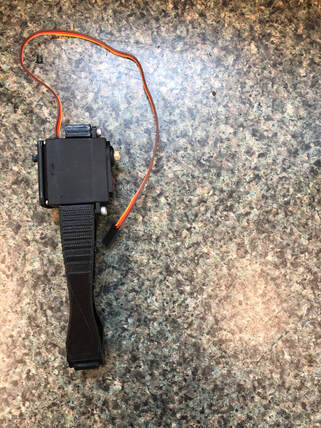
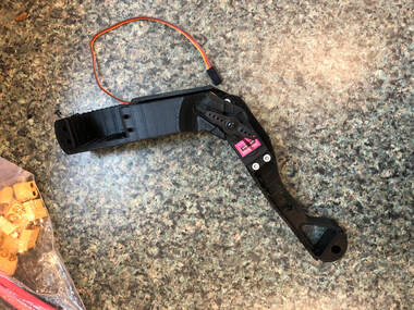
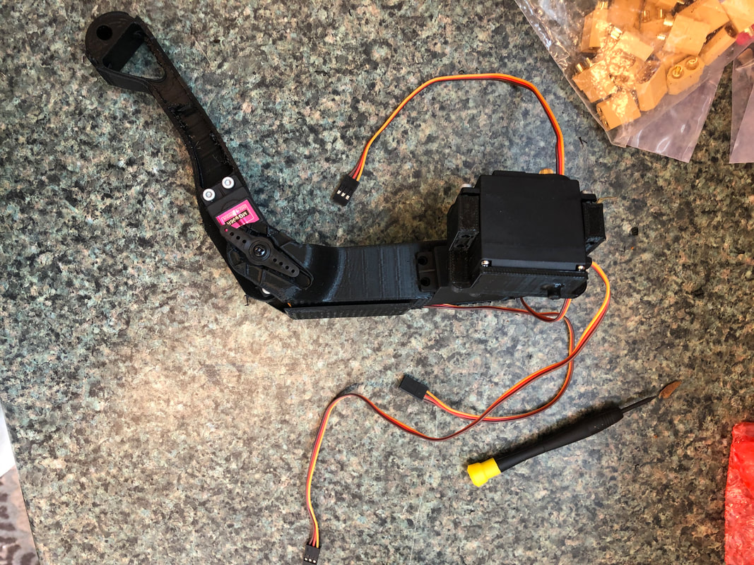
Insert servo into the lower leg and use M3x10 to screw in, I used this screw and it worked well. It is possible that the screw usage is wrong but I have excess of each screw. If this does not work or I encounter failure I will correct this.
Step 2
|
|
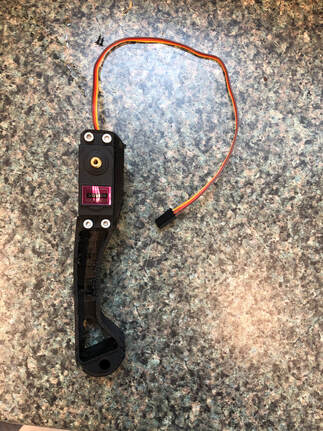
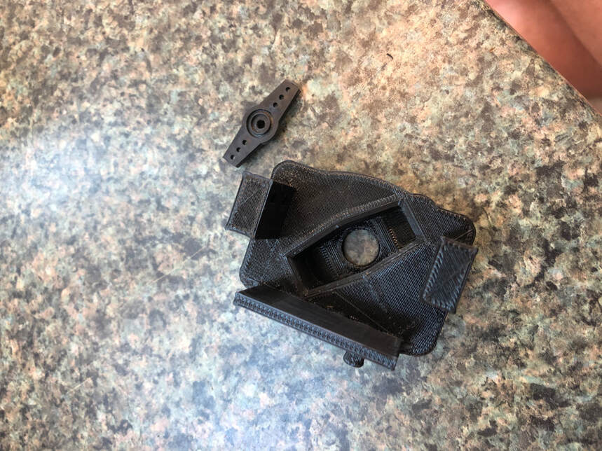
Before you enclose, glue the appropriate servo lever to the accepting port and attach a bearing to the cover, this may mean modifying the lever to suit your needs.
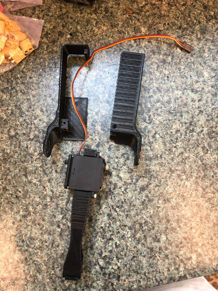
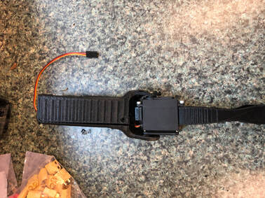
Enclose the part in the upper arm and upper arm cover and screw in the lever (these parts should come with your servo). Screw in an M3x10 screw
Step 3
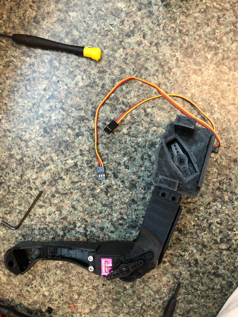
Modify an appropriate lever and glue it into the shoulder.
Step 4
|
|
Insert and screw in a servo to the upper arm and screw in the lever on the shoulder.
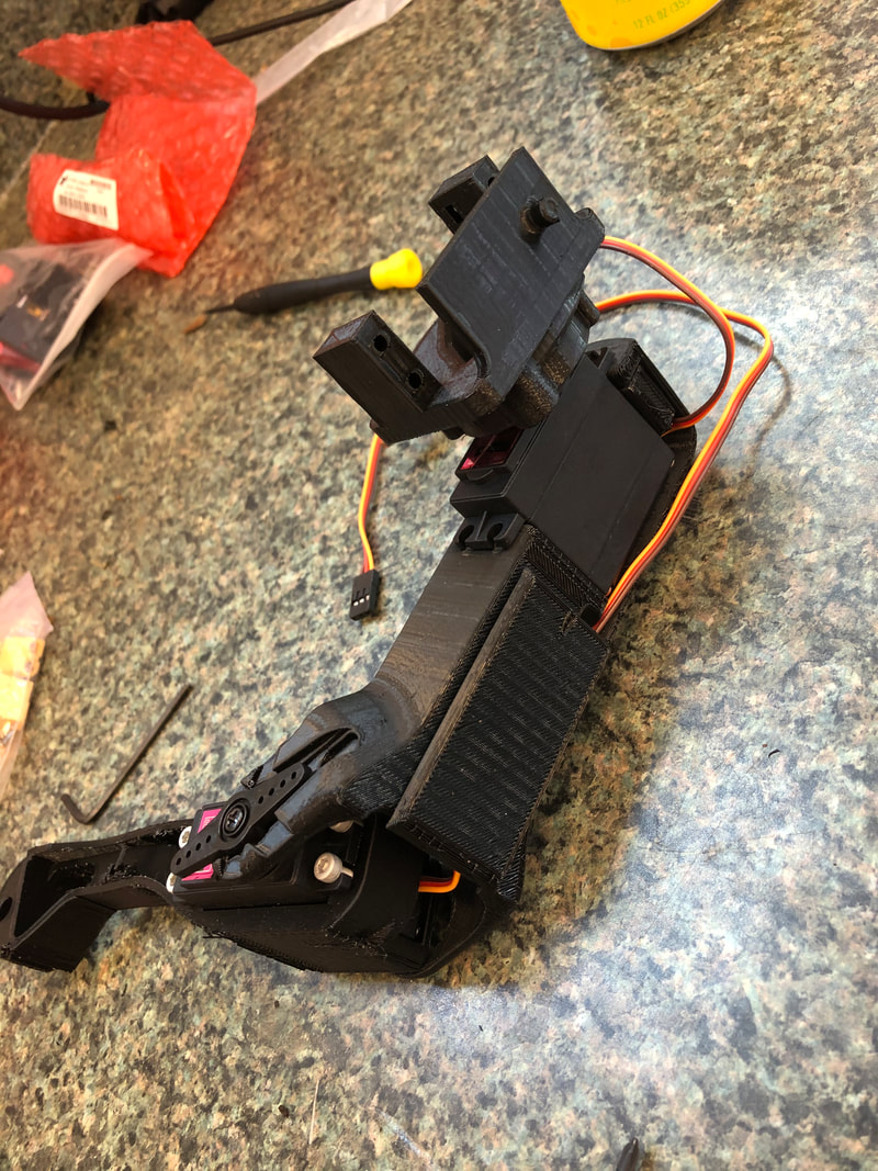
Step 5
Screw in servo to shoulder and repeat steps 1-5 with all 4 legs
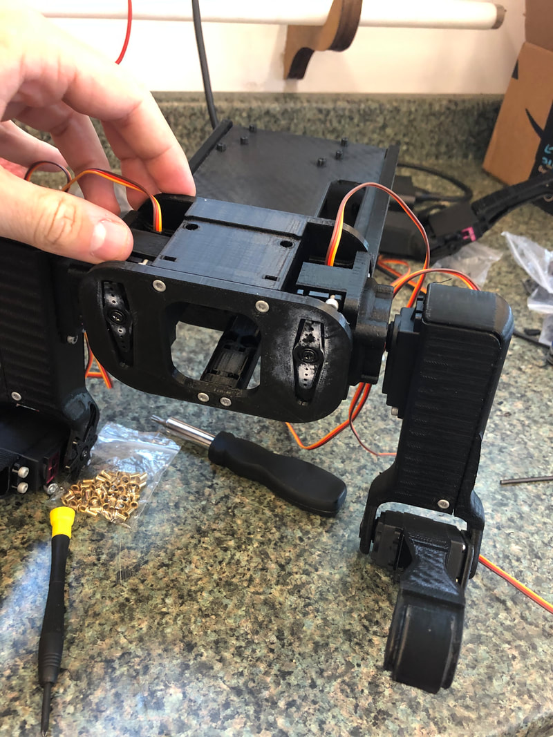
Step 7
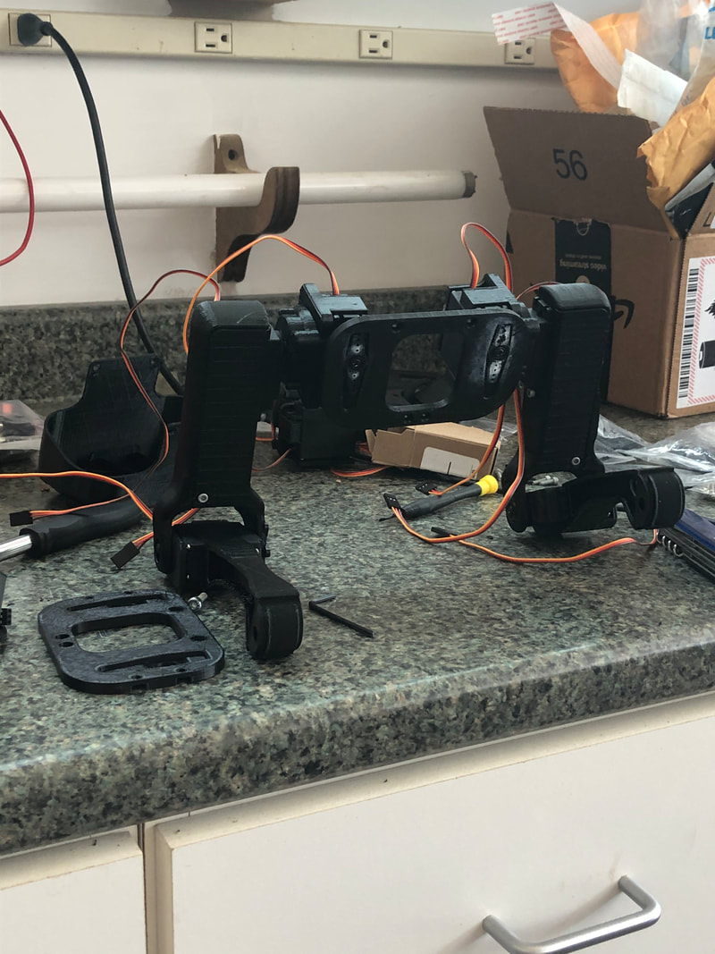
Cut two of the levers to fit the front shoulder plate, which is the plate without holes on the sides. Screw in a right and left arm using the small screws that also came with the servos.
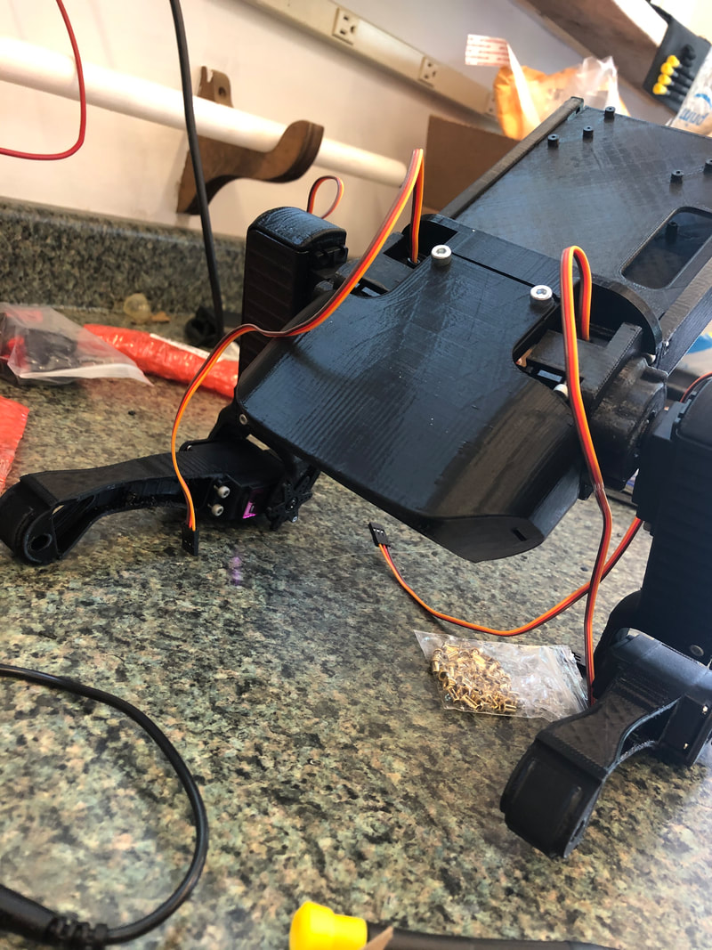
Step 8
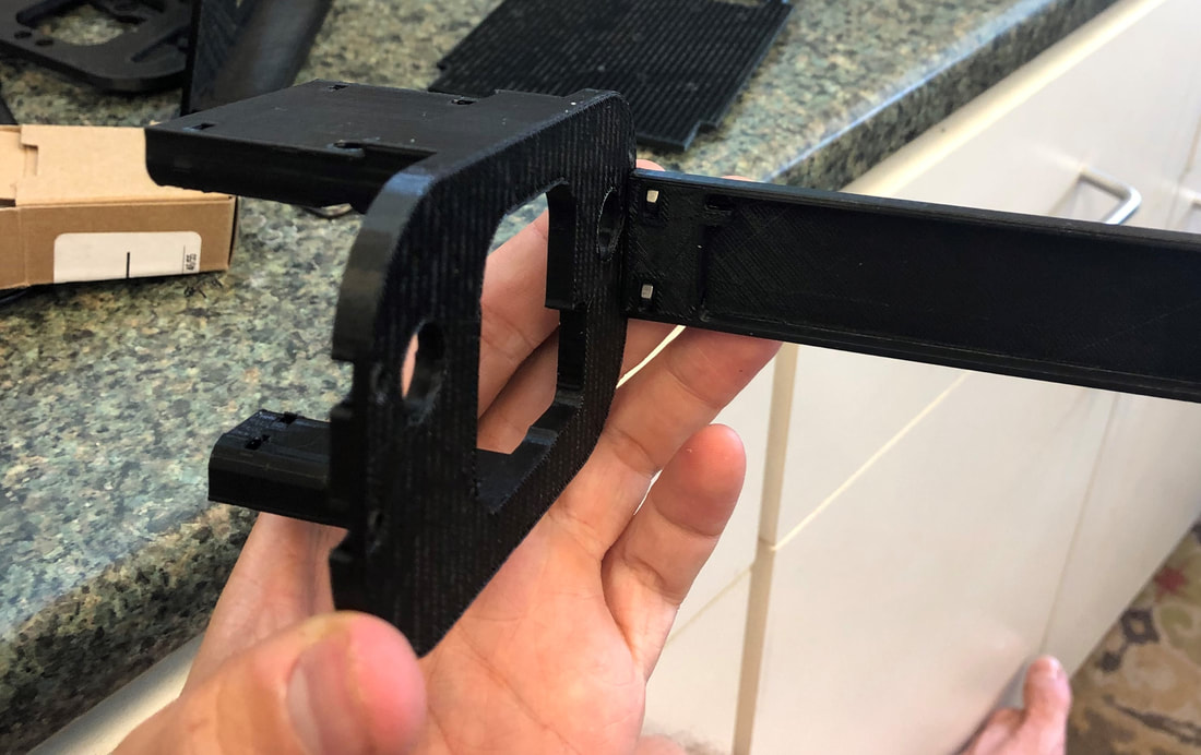
Screw one of the body holders to the front shoulder structure by inserting M3 nuts into the slots and screwing in with two M3x10 screws
NOTE: the image has it upside down, the small rigid slot should be at the bottom. Doing otherwise will make it extremely difficult to screw in the back servos.
NOTE: the image has it upside down, the small rigid slot should be at the bottom. Doing otherwise will make it extremely difficult to screw in the back servos.
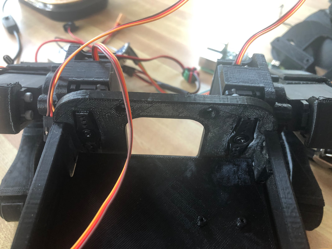
Step 9
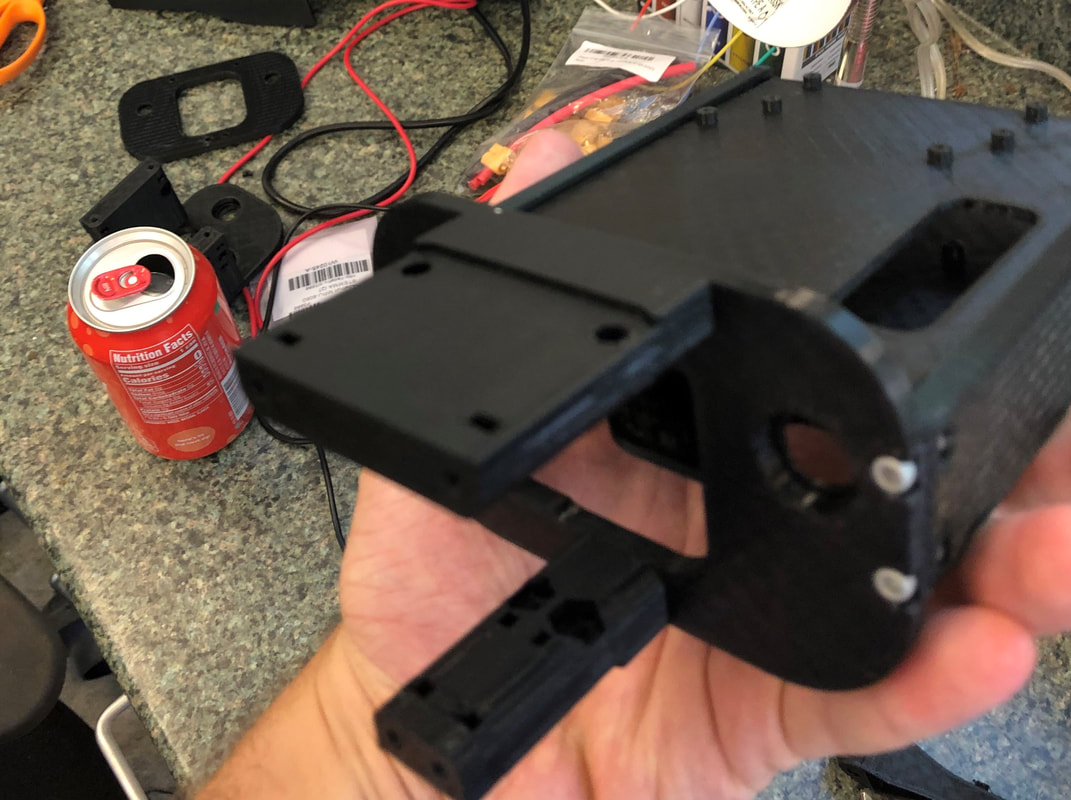
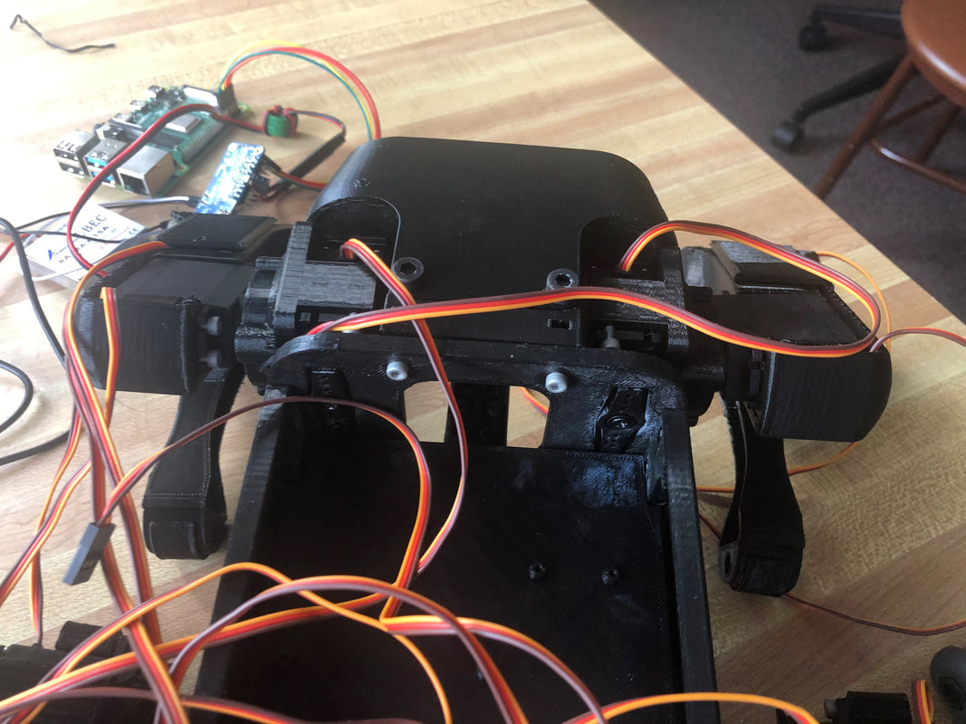
Screw in the other body holder with the electronics mounts placed in the slots. I found that I only needed the on sized for a Raspberry Pi so that should either go on to or be the only one. If you want to eventually add more electronics then do both.
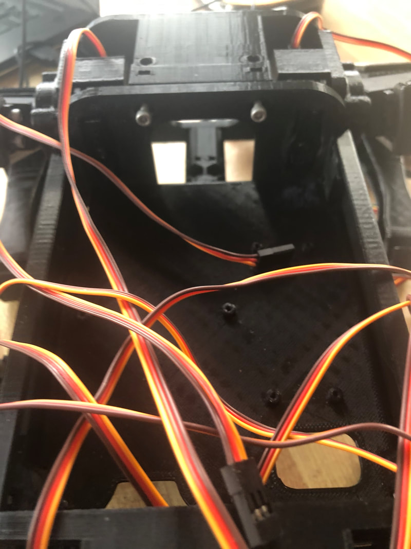
Step 10
Attach the shoulder structure to the shoulder plate using the M3x20 screws.
Step 11
Slip the front face cover over the shoulders. Screw in the top using two M4x20 screws and M4 nuts or two M5x15 screws, I have found that both are effective. Screw in the same bottom way.
Step 12
It is very important that this next step is done in this order.
First: Cut and glue the servo levers to fit the back shoulder plate
Second: Attach the back shoulder plate to the body holders the same way you did the front
Third: Screw in the legs using the screws that came with the servo
First: Cut and glue the servo levers to fit the back shoulder plate
Second: Attach the back shoulder plate to the body holders the same way you did the front
Third: Screw in the legs using the screws that came with the servo
Step 13
Screw on the back shoulder structure using M3x20 screws
Step 14
Attach the back end cover the same way you attached the front
